Nice! I like the "sissy bar". I've been rolling a similar-but-different idea around in my head, to transfer body downforce into the chassis proper. One o' these days.........
.
.
It has been a while since I built a ret-ro F1 chassis, so I figured one was overdue. I also figured it was time to put what I’d learned from the 1229’s into the next F1 design, most particularly the moving of the VSWT control box from the center-guide structure onto a forward extension of the motor box. And, like the 1229’s, it was definitely time to build an F1 chassis framed using 0.039” wire.
Unlike my previous F1’s, that were all 4.0” wheelbase and 5.0” RAX-GPC, this chassis was going to get shortened, still following that “hunch” from the 1229’s, to a 3.875” wheelbase and a 4.875” RAX-GPC.
Reality check:
1) Shortened chassis…
2) Smaller 0.039” wire…
Okay... yeah… right…
You see, there is still that small matter of the final RTR car having to meet the blingin-blangin-frangin 100g minimum weight for F1’s… But there finally just came a point where I said some nasty expletives about minimum weight rules, and decided I wasn’t going to give a rat’s patoot about it; the chassis was going to be what I wanted, and not something else…
In any case, to simplify matters I’ve designed the chassis to fit under a straight-sided F1 body, in this case the ever-popular Parma Matra F1.
Anyway, the A212-c2 came out like this:
Once again, it ain’t much to look at… That’s a few wires, don’t you think? Also once again, I took build sequence photos (they really do help me remember what I did, so I don’t have to think about it the next time), and also also once again I’ll post them up if I get the chance.
Dirty details (done dirt cheap): All wire is 0.039” except as noted. Side pan movement restrictors are 0.055” wire in 1/8” square brass tube. The two VSWT bracing wires and the foremost wire of the center-guide section are 0.047” wire. Center-guide pan up-stops, front-axle rail down-stops, rear indirect main rail up-stops, rear pin mount medial movement stops, and VSWT spring wire are 0.032” wire. Center-guide spring wire, front indirect main rail spring wires, center-guide flanking pans spring wire, rear indirect main rail spring wires, rear pin tube spring mounts, and the “sissy bar” are 0.024” wire. The four motor box assembly pans (two forward, two lateral) are 0.010” brass sheet. Motor bracket is a modified JK (JK-D3F122) and is mounted at an angle to achieve a non-hypoid gear mesh, but keeping the motor mass as low as possible. Guide tongue is a Slick 7 (S7-25) mounted on a 0.025” brass plate above the center-guide section framing wires.
And, drum roll please, the roller chassis as pictured weighs in at 65.7 grams… My guess was I was going to end up between 98 - 99 grams… So when I put the car together I put a heat sink on the motor right away… and the RTR car came in at 100.0 grams…
Of course, I can always add weight at the static pans if I decide to go down that road…
First things first. The raceway is closed tomorrow, so I’ll head over there on Thursday and see what this thing will do…
Consider yourselves forewarned…
Rick
Nice! I like the "sissy bar". I've been rolling a similar-but-different idea around in my head, to transfer body downforce into the chassis proper. One o' these days.........
Hey Tex.
The good old sissy bar still finds its way onto a lot of my chassis, especially the ones built to have one specific body mounted to them. I’ve been sticking them on since I saw the first guy at my raceway (who knows which one, we were all nuts) do it back in ’67. Even my last two anglewinder chassis I built in ’69 had sissy bars (one for a Ford Mk IV and the other for a Marcos Mantis).
The early sissy bars were “big” wire, typically 0.064” and up, because everyone thought “Big = Strong”. Wrecks could be pretty horrific as we kept trying to build cars to keep up with the motors that kept getting faster and faster (at least before they burned, melted or exploded). The sissy bars weren’t the only thing bent completely out of whack… But that was normal back then, since we built another chassis practically every week…
The first time I used 0.024” wire for a sissy bar it looked pathetically small… but they’re light and much more resistant to deformation than I would have first believed. Plus they’re easy to repair, and in extreme cases are easy to remove. I still just solder them to the rear axle tube, and on some in-lines to the rear gear guard wire, depending on whether I want a narrow or wide sissy bar.
I’ll be looking forward to see what new “mousetrap” you come up with…
Finally got this thing on the King track at SCR-Pinellas today…
The last two times out racing F1’s I used the A209(M7) and A209(L). These two chassis/cars are so similar in performance that the only reason I ran one over the other was one was quicker to set up on that track on that day. The A209’s are a F1 chassis design incorporating the CanAm 1225’s design elements, much like the A212-c2 design of this thread is based on the CanAm 1229’s. So as a matter of consistency I used the A209(M7) as the benchmark for comparison against the A212-c2 today. I also had to keep in mind the A209 is a 0.047” wire frame chassis, while the new A212-c2 is a 0.039” wire framed chassis.
While it is true the A212-c2 has a 1/8” shorter wheelbase and RAX-GPC (but the same 1” guide lead) than the A209, as many of you know I have never been able to observe or quantify any performance difference between the same chassis designs with differences in these dimensions, so…
So… I was expecting to see similar differences as I had seen between 0.039’s and 0.047’s, as well as those between the 1229’s and 1225’s…
And that was what happened. Like the 1229, the A212 is a more stable platform than the A209, easier to dial in and smoother to drive, along with all the improved driving characteristics of a 0.039” wire frame. Today, with the track conditions as they were, and with two very similar motors in the two cars, this translated into a difference where the A212 was turning lap times of almost a full tenth of a second faster than what was a very good running A209.
And that was good enough for me.
Obviously, hindsight being 20/20, I should have built F1 chassis out of 0.039” wire and with the VSWT on a motor box extension some time ago… Better late than never…
I don’t know at this time if it will be possible to fit the design elements of the 1233 CanAm chassis into a F1 chassis design… But, after today, I’m definitely going to be giving the thought some time…
This is fun!
Rick
I'd ask for the color graph paper drawing, but it'll be so long before I ever get around to building one of your creations(I have 4 more of my own to do first... that's a couple of years at least in "Tex work ethic time"), that you'll have a new "best" chassis 3 generations down the road... might as well wait 'til then.
I admit it… It’s pretty difficult to follow what is going on with these chassis just from the pictures of the completed chassis… And the diagrams are getting pretty basic, because at this point I know which lines are the ones I really need to pay attention to… and in the case of this F1 chassis the diagram are those few lines only!
So, hopefully this series of build sequence pics will help anyone so inclined to get a better idea what it is that was built into this thing. Again I apologize for the blurry photos made in haste. Have fun!
Pictures 1 - 5:
Front Spanning Wire Assembly; The front spanning wire for this chassis consists of four wires soldered together.
Pictures 1 & 2: The first 2-bend front spanning wire is fashioned, assuring it is flat, and taped into place.
Note: The outer maximum width of the chassis is set (wide brass plates) and spacing on both inner sides of these (two 0.047” wires and one 0.25” wide strip of brass) defines the maximum width of the Front Axle Rails (reference Picture 6).
Picture 3: (Blur…) Two 1-bend wires are soldered to each diagonal side of the first wire in Picture 1 & 2, projecting forward but spaced with another piece of wire 0.039” inside of the maximum chassis width.
Pictures 4 & 5: Another 2-bend wire is fashioned, assuring it is flat, and soldered to the rear aspect of the first three wires. This completes the front spanning wire assembly.
Picture 6: The three straight wires comprising each Front Axle Rail are soldered together (but not to the Front Spanning Wire Assembly).
Note 1: On the long lateral-most wire, the rear length is longer than needed to allow for a rear axle tube upright bend later.
Note 2: On the two shorter more-medial wires, the rear length is only slightly longer than needed and will be trimmed to fit when the Center-Guide Section is made.
Pictures 7 - 14:
Center-Guide Section:
Pictures 7 – 10: Center-Guide section main framing
Pictures 11 - 12: Center-Guide section flanking pans
Picture 13: Guide tongue installation
Picture 14: Center-Guide section installation
Picture 7: The center-guide section is started with two straight wires tack-soldered together perpendicular to each other; the first short wire is parallel and just behind the center length of the front spanning wire and is 0.047” wire (0.047” wire is used to give the guide tongue a slight upward tilt later); the second wire runs rearward from the first along the chassis center-line, and is longer than needed to ease installation (and is trimmed to size later). No portion of the center-guide section is attached to any other part of the chassis framing until later.
Picture 8: Two 1-bend wires are soldered to the first two to complete their connection. Note: The length of these wires parallel to the center-line wire is only about 0.625”, and not the entire length of the structure.
Picture 9: A 2-bend wire is shaped to fit from each side of the center-line wire and paralleling the long wire of the Front Axle Rails and beyond the position of rear axle tube; the excess length is used to make a rear axle tube upright later. At this time this wire is soldered to the center-line wire only.
Picture 10: A 1-bend wire is shaped to fit each of the lateral sides of the two forward lengths of the 2-bend wire from Picture 9 and the 1-bend wire from Picture 8 where it parallels the center line; The rear ends of the two shorter wires of the Front Axle rails are trimmed to allow clearance with this wire; it is soldered along its entire length.
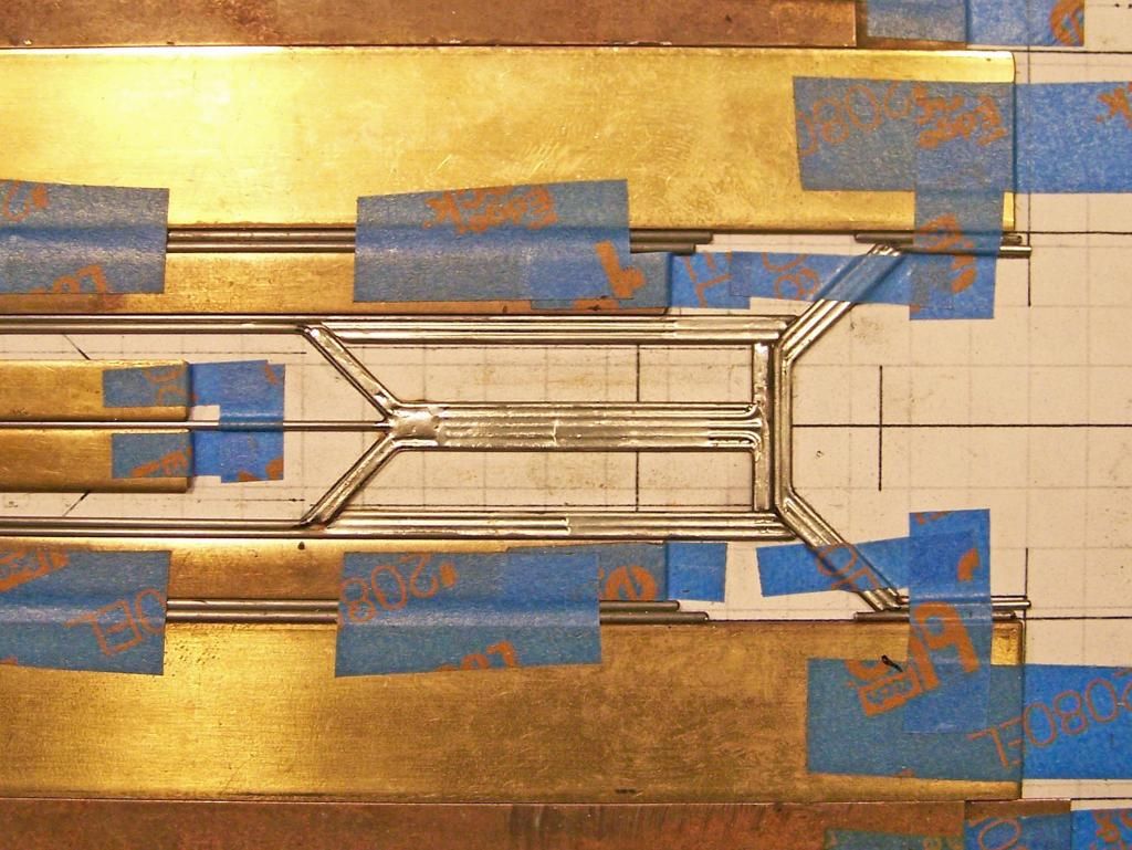
Picture 11: The two Center-Guide Flanking pans each consist of a 1-bend wire attached to the front of the Center Guide Assembly and projecting rearward along the lateral aspect, and filled with another five straight wires.
Note 1: The medial-most straight wire is soldered to the adjacent center-guide assembly approximately 0.5” along its forward length.
Note 2: All center-guide flanking pan wires are soldered together approximately 0.5” along their forward and rearward lengths.
Note 3: All medial, rear and lateral aspects of the center-guide flanking pans are trimmed to ensure clearance (minimal) with adjacent wires.
Picture 12: A 1-bend 0.032” wire is soldered atop each of the two diagonal lengths of the center-guide framing to act as up-stops for the center-guide flanking pans.
Picture 13: A piece of 0.025” brass plate is tinned and soldered atop the front (approx. 0.375”) of the center-guide section (it is easier to make this piece larger than needed and trim it to fit). The guide tongue (Slick 7 S7-25) is tinned and then soldered in place.
Picture 14: The 7/32” D x 1.47” L rear axle tube is jigged into place. The rear axle tube upright bends are made on the center-guide section and soldered to the front of the rear axle tube (ensuring there is minimal clearance between the front of the center guide assembly and the front spanning wire assembly).
Picture 15: The rear axle tube upright bends are made on the front axle rails and soldered to the rear of the rear axle tube (again ensuring there is minimal clearance between the front of the front axle rail assembly and the front spanning wire assembly).
Picture 16: The rear portions of the adjacent wires of the front axle rails and the center guide assembly are soldered together (to a point approximately 1.5” forward of the rear axle center-line).
Pictures 17 - 25:
Indirect Main Rails (IMR); The indirect main rails (or “z-rails”) for this build are a 2-1-2 set-up (2- wires project forward from the chassis rear assembly; -1- connecting wire in-between; -2 wires attach to the front chassis assembly). They also incorporate framed areas at the rear-lateral aspect for the addition of pans later.
Pictures 17 & 18: The first IMR straight wire (with rear axle tube upright bend) is soldered to the front of the rear axle tube and to the adjacent rear length of the front axle rails (approximately 1.5” forward of the rear axle center-line).
Picture 19: The jig is removed.
Note: Two 0.039” wires are added on each side as spacing inside of the brass for maximum chassis width for placement of the second IMR wires (Pictures 20 & 21).
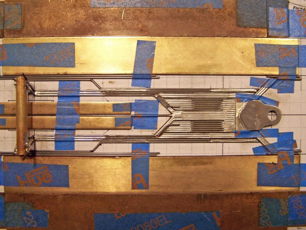
Pictures 20 & 21: The second IMR 2-bend wire is shaped to lie adjacent to the forward length of the first; the bends outline the rear-lateral pan area; the second IMR wire is soldered to the adjacent front and rear of the first IMR wire (Picture 20), and to the rear of the rear axle tube (Picture 21).
Last edited by CMF3; 04-08-2014 at 12:23 PM.
(Pictures 20 & 21, continued)
Picture 22: The spacing wires are removed.
Picture 23: The single straight IMR connecting rail is soldered to the forward portion of the first two wires.
Note: The front and rear lengths of this wire are trimmed to ensure minimal clearance with the front spanning wire assembly and the second IMR 2-bend wire.
Picture 24: The first of two 1-bend IMR wires that attach to the front chassis assembly is soldered to the rear of the IMR connecting wire and to the front spanning wire assembly.
Note 1: A piece of 0.039” wire is used as spacing inside of the brass for maximum chassis width at the front of the chassis.
Note 2: The rear length of this wire is trimmed to ensure minimal clearance with the second IMR 2-bend wire.
Picture 25: The second of the two 1-bend IMR wires that attach to the chassis front assembly is soldered to the rear and front portions of the adjacent first 1-bend IMR wire from Picture 24.
Note 1: A piece of 0.039” wire is used as spacing inside of the brass for maximum chassis width at the front of the chassis.
Note 2: The rear length of this wire is trimmed to ensure minimal clearance with the second IMR 2-bend wire.
Pictures 26 - 28:
Side Pans: These consist of three straight wires attached to the front spanning wire assembly.
Picture 26: The first lateral side pan wire is soldered to the lateral side of the spanning wire assembly. The second middle side pan wire is soldered to the rear and forward adjacent lengths of the first wire.
Note: The rear of these two wires extend along the lateral side of the second IMR 2-bend wire to approximately 7/16” forward of the rear axle center-line.
Picture 27: The third medial side pan wire is trimmed at the rear to ensure minimal clearance with the second IMR 2-bend wire, and is soldered to the rear and forward adjacent lengths of the second wire.
Note: The excess length of the center-guide section center wire could be trimmed off at this point.
Picture 28: A piece of 0.024” wire is soldered between the front of the side pan (third medial wire) and the adjacent IMR wire.
Pictures 29 - 34:
Motor Box / Extension:
Picture 29: The motor box extension is started with two wires tack-soldered together. The first is a 1-bend wire just behind rear of the center-guide section, and is made to allow a tiny gap between itself and the adjacent center-guide section wires. The second is a straight wire running from the angle of the first rearward along the chassis center-line; and again longer than needed to ease installation (and is trimmed to size later).
Picture 30 & 31: A 1-bend wire (with rear axle tube upright bend) is soldered to each lateral length of the first wire; it too should fit with a tiny gap between itself and the forward portion of the adjacent center-guide section wires; its rear length is soldered to the adjacent center-guide section wires (Picture 30), and it is soldered to the rear of the rear axle tube (Picture 31).
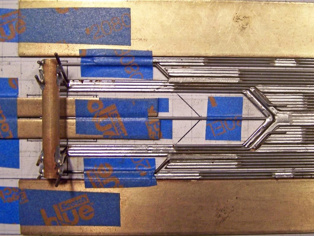
(Pictures 30 & 31, continued)
Picture 32: A 2-bend wire is soldered to each side of the center-line wire and to the rear length of the wires from Pictures 30 / 31.
Picture 33: A 1-bend wire is soldered to each of the two forward lengths of the wires from Picture 32.
Picture 34: A 1-bend wire is soldered to each of the two forward lengths of the wires from Pictures 30 / 31.
Picture 35: The 4-bend (2-plane) rear gear guard wire and the 2-bend rear axle tube spreader wire are soldered in place.
Picture 36: The front axle rail down-stops are installed. Two pieces of 0.032” wire are soldered side-by-side for a distance shorter than the distance from the front spanning wire to the center-line of the front axle (this is where the spanning up-stop wire for the center-guide section / IMR’s will run later). Carefully these are soldered atop the foremost portion of the front-axle rails (only!), ensuring they rest atop but no solder gets onto the front spanning wire assembly (or adjacent IMR’s).
Note 1: It is easier to make these longer than needed, and to cut the forward excess length off after installing.
Note 2: The forward front-axle upright will be placed atop these down-stops at a later step.
Picture 37: A 1-bend wire is soldered atop each of the forward edge of the angled and forward portions of the front spanning wire assembly. These wires act as lateral movement restrictors for the guide and the front axle rail down stops.
Picture 38: The excess of the front axle rail down-stops is removed.
Picture 39: Six small 0.024” bump-wires are soldered into place: two on the center-guide section, one each on the forward floating portion of the IMRs, and one each on the IMR wires connecting to the front spanning wire and side pans. (Note: No bump-wires are attached to the front-axle rails.) These bump-wires abut against the underside of the spanning up-stop wire for the center-guide section and IMR’s
The 2-bend spanning up-stop wire for the center-guide section and IMR’s is soldered in place (lateral sides only); it is placed along the line of the front axle, which will be suspended above it, and rests atop the bump-wires.
Picture 40: Four pieces of 0.010” brass sheet are cut to fit the sections (rear lateral) between the IMR wires and the two quadrangular sections of the motor box extension, and soldered in place.
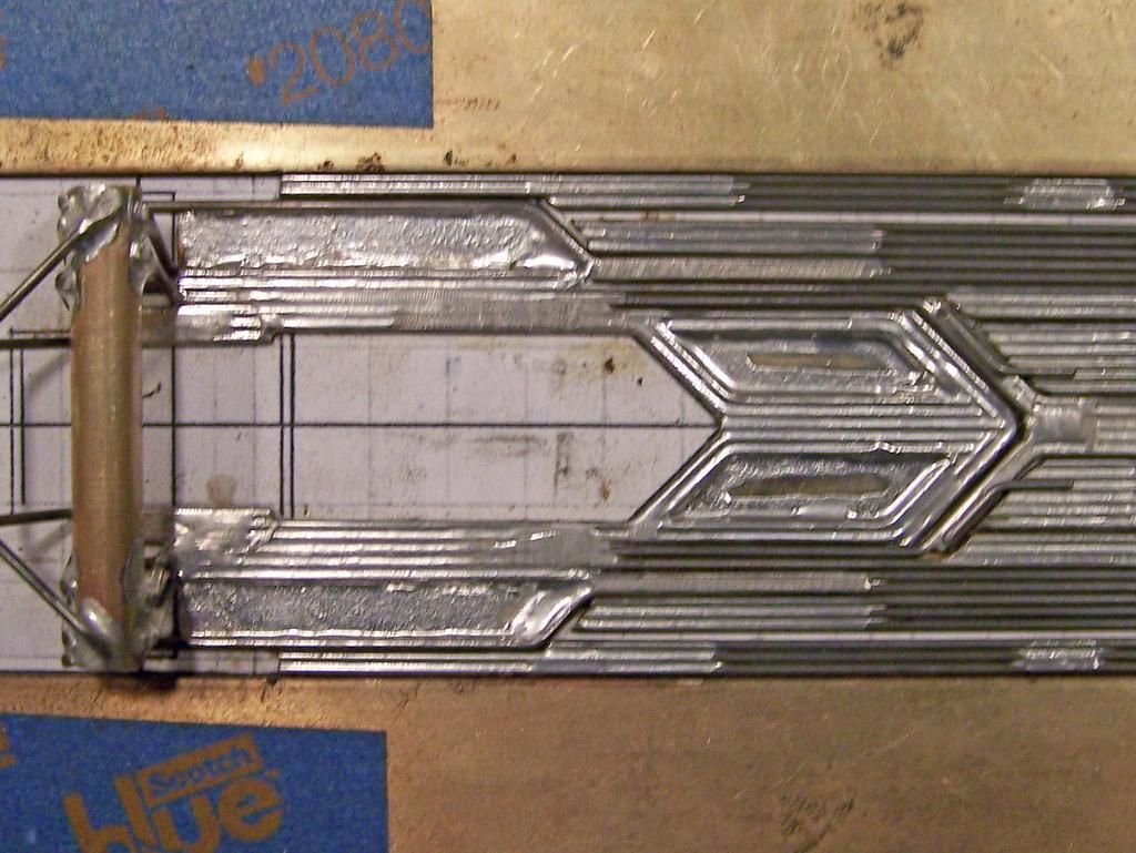
Picture 41: The center portion of the rear axle tube is removed. The motor bracket (JK-D3F122) is modified and positioned so the motor will be angled such that the shaft of the motor will be perpendicular with the rear axle while keeping the front of the motor flush with the bottom plane of the chassis, and soldered into place; this allows for a better gear mesh than with an offset, or “hypoid”, motor mounting gear mesh, while keeping the mass of the motor as low as possible.
Picture 42: A short wire is soldered atop each side of the motor box; this helps to cradle the motor and affords easier points to solder the motor in place.
Picture 43: The control box for the variable spring-wire tension (VSWT) system for the front axle rails is soldered atop the center-forward wires of the motor box extension; the control box is a 1/8” square brass tube cut 5/8” long with a 1/16” hole drilled in one side 5/32” from the front of the tube. (A FK-type motor mounting screw will be tapped into the drilled hole and used as the adjuster for the VSWT.)
Picture 44: A 2-bend 0.047” bracing wire is soldered to each side of VSWT control box, atop the motor box extension and to the back of the chassis (forward of the motor bracket); this wire helps to stiffen the motor box extension, counteracting the forces exerted on it by the VSWT spring wire.
Picture 45: The side pan movement restrictor box is soldered to the main framing adjacent to the motor bracket sides; the restrictor box is 1/8” square brass cut to approximately 0.30” - 0.35” length. A 2-bend piece of 0.055” wire is soldered to each of the side pans so they extend into the movement restrictor box; they should just make contact with the inner side of the square brass tube. This completes the outer perimeter side pan movement restrictors.
Picture 46: A 1-bend 0.032” up-stop wire is soldered to the rear of each of the medial IMR wires to rest atop the rear of the lateral floating IMR wires. A 0.024” spring wire is soldered to each of the lateral floating IMR wires to rest atop the up-stop wire. Note: These spring wires are set to “zero-tension” when in their “static” or at-rest position.
Picture 47: A U-shaped 2-bend 0.024” spring wire is soldered to the medial rears of the center-guide flanking pans so that it wraps around the VSWT control box. Note: This spring wire is set to “zero-tension” when in its “static” or at-rest position.
Picture 48: A 0.024” spring wire is soldered to the center-guide section and one each 0.024” spring wire is soldered to the two forward floating sections of the IMR’s, so that they rest atop the spanning wire up-stop. Note: These spring wires are set to “zero-tension” when in their “static” or at-rest position.
Pictures 49 - 51: The spanning front axle (FAX) uprights add lateral strength to the chassis; they are also angled away from perpendiculars for greater strength; the spanning uprights also make axle setting/changing easy.
The 4-bend (2-plane) front FAX upright is soldered atop the front axle rail down-stops.
The 4-bend (2-plane) rear FAX upright is soldered atop the front axle rails.
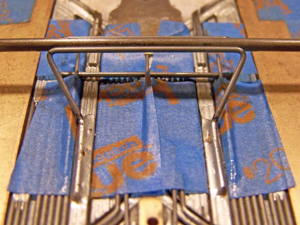
(Picture 49 - 51, continued)
Picture 52: A 2-bend wire is soldered atop the base of the rear FAX upright. Note: This spanning wire should not contact the center-guide section spring wire below it. (This wire is to allow contact points for the VSWT spring wire; see Picture 53.)
Picture 53: Two small (0.125”) pieces of 3/32” square brass tubing are soldered to each side of the rear FAX upright base spanning wire. These are the forward contact points for the VSWT spring wire.
Picture 54: Raised Side Wires: A side view of the chassis showing straight wires soldered along the lateral edges (the gap between the two sections is where the spring-mounted rear pin mounts are placed):
1) 2x high at the rear of the side pans (forward of the 0.055” restrictor wires, rearward of the rear body mount pin tubes placement); these wires help prevent the body moving atop the side pans;
2) 4x and 2x high forward of the rear body pin mount spring wires placement; these wires raise the placement of the middle and front body mount pin tubes above the chassis superstructure they must span and not interfere with. (Note: the height of the front pin tube was miscalculated and an additional wire had to be added forward of the front axle to raise it higher, reference Picture 58).
Picture 55: The 1-bend 0.032” is soldered just medial to the lateral edge and between the raised side wire sections; this wire acts as a medial movement stop for the spring-mounted rear body mount pin tubes.
Picture 56: The spring-mounted rear body mount pin tubes are constructed and soldered in place:
A 3-bend 0.024” soldered to a 0.039” support wire atop which the 1/16” brass pin tube is soldered with a 1/16” collar at its lateral edge (excess length to be trimmed later). The spring wires are soldered to the side pans approximately 1.125” forward of the pin tubes.
Note 1: The lateral portion of the spring wire is lateral to the medial movement restrictor wire (from Picture 55).
Note 2: The support wire must be placed (trimmed if necessary) so that it does not interfere with the rear IMR spring wires.
Note 3: The medial ends of the pin tubes are trimmed to ensure minimal clearance between each other.
Picture 57: The middle body mount pin tube is soldered atop the raised side wires, ensuring it will allow clearance for the VSWT spring wire (Picture 59).
Picture 58: The front body mount pin tube is soldered atop the raised side wires, ensuring it will allow for clearance of ALL the chassis parts it must span…
Note: While it was found the original placement of the pin tube did allow spacing for the guide tongue, the base of the front FAX upright just made contact with the bottom of the front pin tube… Though probably sufficient, it was decided to add another wire to the front of the raised side wires to further raise the height of the front pin tube to ensure there would be no question as to the amount of clearance…
Picture 59: The 5-bend 0.032” VSWT spring wire is fashioned and inserted into place. A FK-type motor mounting screw is tapped into the VSWT control box, and is used to adjust the tension on the VSWT spring wire.
Addendum:
And that’s it…
Just a question of mounting the front axle and wheels, adding all the other usual runny bits, and sticking the body on it.
While the A212-c2 is not quite as painful as the build sequence for the 1229 or 1233, still if you have any questions, fire away.
Now go medicate yourself…
Rick
Bookmarks